Physics at Manoa Falls: Nuclear Physics

Although I usually view the world on the macroscopic level, this physics chapter of nuclear radiation has got me thinking about the microscopic processes that are occurring in my daily lives. Of course I am not daily exposed to any dangerous radioactive emissions, but I do see the decay of carbon almost every day. However, I remember the specific time when I saw a decaying tree trunk on one of my family hikes at Manoa Falls.

Although they don't know it, My sister and her husband stand before a partially decaying tree that is undergoing carbon decay

Although they don’t know it, My sister and her husband stand before a partially decaying tree that is undergoing carbon decay

The tree trunk was cut down and laid on its side, left to rot for the next few years. By the looks of the soggy wood, we could tell that the trunk has already been decaying for a few years. At the time I was only interested in climbing the giant trunk that overlooked the rushing Manoa stream, but now after studying about the microscopic processes that occur during decay I can fully understand how the trunk was decaying at the atomic level.

Before the tree was cut down, it was alive and accepting the element nitrogen through the soil from a process called nitrification. The addition of the extra and free neutrons created carbon-14, one of the isotopes of carbon-12. In this process the a neutron is added to the nitrogen, already containing an atomic mass of 14. This addition causes the nitrogen to emit a proton, transmuting it to a carbon atom with the same atomic mass but a proton count of 6 instead of 7. The emitted proton and the added neutron create a hydrogen atom.

However, when the tree is dead it can no longer absorb nitrogen from the ground. Instead the once created carbon-14 begins to decay. The decay involves the carbon atom emitting a single electron, causing the atom to be slightly positive. Therefore, the atom will regain a proton returning to its nitrogen atom state. Over the years the amount of carbon will decrease until there is only a small amount remaining.

However, I could not see this process occurring during my time watching the massive decaying tree trunk, because this process, not only occurred at the atomic level, but it also occurred extremely slowly. The half-life for carbon decay is own to be 5,730 years. This means that when half of a sample’s carbon amount decays or when only half is left, 5,730 years would have elapsed. Then when half of the half of the sample would be left, the same amount of time would have elapsed. The process for all decaying matter is characterized by an exponential decay rate. The equation for finding the samples half-life also includes the initial and final amounts of the sample and the time that has already elapsed. Also another form of the equation gives the decay constant, that tells how much matter of the sample would be remaining after a given time. The equation is listed below:

image

Carbon-14 dating can be used to accurately date artifacts to millions of years old. However, since the tree trunk that I saw was only a few years into its decay process, it would be hard for the dating process to get a decent estimate on the trunk, because only a minute amount of carbon would have decayed. Still in a few thousand years carbon-14 dating could be effective in determining the age of the trunk.


My sister posing with the decaying tree trunk

My sister posing with the decaying tree trunk

Physics at Kailua Beach: Light as a Wave

Good thing Jessica brought her polarized glasses to the beach.

Good thing Jessica brought her polarized glasses to the beach.

At our last class day at Kailua Beach, I had a great time hanging out with my friends in the sun.

However, at that moment I didn’t realize that I was witnessing a physics phenomenon with my very own eyes, or at least with my eyes through a polarized filter on my sunglasses. At the beach I viewed the sunlight being polarized in three ways: scattering, reflection, and absorption.

Originally, all light in its natural state is unpolarized, meaning that the light ray has wavelengths traveling in all directions. Since light is a transverse wave, an ordinary light wave is incoherent, forming a mess of disoriented waves with various lengths, orientations, and phases. However, the light that we see is generally in waves that are coherent and monochromatic or having the same wavelength.

At its source sunlight is unpolarized, but as the light rays travel through the universe to reach planet Earth the light becomes polarized. The light is polarized by scattering, because as the light travels through air it interferes with the air’s atoms. This interference will cause the atoms’ electrons to vibrate, emitting new electromagnetic field. This absorption and emission process will cause scattering of light, and this scattered light is partially polarized. The scattered light is also the reason why we see the sky as blue. Because the horizontal part of the electric field vector in the wave will cause the charges to vibrate horizontally, the light is horizontally-polarized.

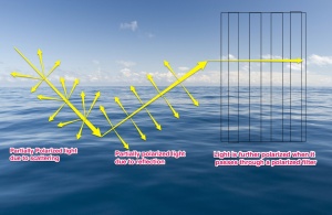
At the beach I also witnessed sunlight being polarized by reflection, which occurred when the partially polarized sun beams were reflected off the oceans surface. The light reflected off the water was partially polarized. The degree of polarization depends on the angle the light hits the plane of the water. At incidence angles 0 and 90 degrees no polarization occurs, but for angles between 0 and 90 degrees some amount of polarization occurs. To achieve the position where the beam of light is completely polarized we must apply a particular angle, or Brewster’s Angle.

Light can be polarized by reflection on a surface

Light can be polarized by reflection on a surface

At the beach the reflected light left the water parallel to the surface, therefore the light became horizontally polarized and left a glare on the ocean. Luckily, I brought my polarized sunglasses to counter this glare. The last type of polarized light I saw was through my sunglasses. Since the light reflected from the ocean was horizontally-polarized, I needed vertically-polarized filters to impede the wavelengths of light. The filters on the glasses lens are polarized in a specific direction, so that it can stop the light polarized in the direction perpendicular to the filter’s polarization. Because my polarized sunglasses only had a filter made for vertically-polarized light to be absorbed, it can only cut 50% of light. But since most of the reflected light was horizontally-polarized my sunglasses could cut most of the reflected light. Therefore, when I viewed the beach scenery through my polarized lenses, everything was not as bright, because I was only seeing a small fraction of light that was absorbed through my glasses.

Julia and me protecting our eyes with vertically-polarized sunglasses.

Physics at Windsor Castle: Optics

On the ‘Iolani orchestra trip to London this past winter, our travel plans included a tour of the

famous Windsor Castle. Although the hundred year old castle was supposed to be the main

attraction, many of the students were more fascinated by the giant lake surrounding the castle
grounds. I was one of those students intrigued by the lake’s fish, duck, and goose population. At

the time I enjoyed observing nature’s creatures interact with the serene lake, but now I realized

that nature wasn’t the only factor in creating the scene’s interesting optic effects. The physics of

optics and how people perceive images of light also helped to create the the visual scene of the
lake.

The blurry image of the trees on the lake are caused by diffuse reflection.

The blurry image of the trees on the lake are caused by diffuse reflection.

We perceive images when light reflects off a surface and hits our eyes. When I looked across

the vast lake I saw a blurry image of the trees and castle surrounding the lake. I perceived an

image because light that came from these objects traveled to the surface of the lake and then

reflected off into my eyes creating an image. However, the reflection was blurry because diffuse

reflection took place, because the uneven rippling surface of the lake reflected the light rays in

various directions. Therefore, the light beams diverged instead of reflecting in a orderly parallel

fashion like in specular reflection.

Not only did I look across the surface of the lake, but I also watched the fishes, plants, and

pebbles within the water. Although I saw the objects in the water exactly a I would if they were in

air, my eyes perceived the objects to be in different locations then they actually were. I saw the

image of the object to be further away and higher than the actual object. My misperception was

a result of light traveling at different speeds when it passes through different materials. When

the light rays from the underwater object traveled from the lakes bottom towards the surface of

the lake, it traveled in a straight path. Right when the light transitioned from the material of water

to the material of air, the ray of light bent. The light bends to keep its wave form, this is called

refraction.

Because light bends when passing through different medias, the images we perceive are in a different location than the actual object

Because light bends when passing through different medias, the images we perceive are in a different location than the actual object

The angle of reflection is dependent in the index of refraction for each media the light passes

through. The greater the difference of index of refraction between the two medias light passes

through, the greater the angle of reflection. The water in the lake had an index of refraction

of 1.33 while the index of refraction of air is 1.00. Since the index of refraction if equal to the

speed of light divided by the velocity of the light ray in that specific material, n = c/v, the smaller

the value of n, the greater the velocity if the light in that media. While the lights speed changed

between different medias, the light’s frequency remains constant. So when the light ray left the

lake, it began to travel faster in the air.

When speeding up in the air, the light angle will become smaller as compared to the angle of

lights in the water. With the angle of light created in air, my eyes retraced that ray backwards

into the water, creating a image of the object that I saw. However, the real object was actually

closer to me than where I thought I perceived the image, due to the laws of refraction.

Physics on a Dart Board: Magnetism

When my four sisters visit me in Hawaii, there is always so much to do and so many places to visits. However, on days when we just want to relax at home, we can still find fun activities to entertain ourselves. One of my favorite games I enjoy playing with my sisters is darts. Because real pin darts would make too many holes in our walls from all our miss-throws, we play with a magnetic dart set. We often find ourselves challenging each other for hours with this simple but technical game. However, I need thank the laws of physics for creating the unique properties of magnetism, allowing my family to have tremendous amounts of fun.

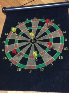
The dart set works by having a metal dart board being attracted to the magnetic parts of the darts being thrown. The darts are permanent magnets, because they not only attract other magnets but also metal materials that are not magnetized. The darts’ magnets all have two poles, a North Pole and a South Pole. Just like in an electrical current, the like poles repel, but the opposite poles attracts. All magnets will always contain these two adjacent poles, because they are inseparable.

Each dart has a magnetic end. The magnet is permanent, and can attract both permanent or unmagnetized metal materials

Each dart has a magnetic end. The magnet is permanent, and can attract both permanent or unmagnetized metal materials

The cause of the magnetism in the darts is caused by a moving or spinning charge in the metal. All electrons are small magnets, and when these electrons do not have an opposite spinning electron to pair with, a magnet will form. However, if all the electrons in a atom have their spins canceled out, then that atom becomes neutral. Since the darts are definitely magnetic, they do have unpaired spinning electrons. When materials has unpaired electrons and becomes permanent magnets they are called ferromagnetic materials. The darts are either made out of copper, nickel, or iron, because those are the only ferromagnetic materials that exist.

In the darts’ magnet the magnetic field is directed from the North Pole to the South Pole and are always in closed loops. However, it doesn’t matter which way the magnetic field is traveling, because the dart board is not a permanent magnet. The board is made from a metal material with a clothe coating, but it cannot attract or repel other non permanent magnets. The use of the not permanent magnetic board, is necessary to ensure that a a field in magnetic board and a magnetic dart will not repel each other. Therefore the set up of the dart set ensures that the darts will always attract the board, thus staying on the board’s surface.

However, when the magnetic darts come into contact with the board, the board becomes temporarily magnetized. Originally, the board’s domains, tiny regions or electron spins, are randomly arranged and face in any directions. When the dart’s magnet touches the board, the board’s domains will align themselves in an uniform matter, because the magnet’s incoming pole will attract the domains’ opposite pole. However, soon after the dart looses contact with the board the domains will rearrange to its usual positions.

The dart board is made from  a not magnetized metal material.

The dart board is made from a not magnetized metal material.

Therefore, the use of a permanent magnet and an unmagnetized metal board helps the game of darts to run smoothly and work properly. There is no need to worry about which way the dart’s magnetic poles are facing when it hits the board, because both the north or south poles will attract the shifting domains in the board.

Physics in Lawn Decor: Current Electricity

Last year in my front yard, I put up three chains of lantern decor hoping to light up the yard at night. When I first set up the lighting decor, I was disappointed with the low quality lights I had bought. The lanterns were very dim and did not provide enough lighting at night; also some lanterns failed to light up. However, I did appreciate the visual appearance of the colorful lanterns. Although I am still disappointed with the lights, I am glad that I can now at least understand why the lights act this way in relation to the physics of current electricity.

The flow of current in lights is dependent on the voltage change and resistance

The flow of current in lights is dependent on the voltage change and resistance

For a lighting system to work, there must be an electrical charge flowing through the lights and the connecting circuit. The circuit’s current is carried by electrons and is the rate at which the charge flows though a point in the conductor. To produce a current there must be a potential voltage difference, causing electrons to flow from high voltage areas to low voltage areas. In each lantern’s bulb there are two filaments connecting to two different sources, providing this voltage difference. Usually, one filament is connected back to the circuit and one off to the side.

The current of the circuit is dependent on the amount of voltage and resistance. Current is equal to the change in the amount of voltage divided by the resistance, I=V/R. Since the lights are connected to an external electrical source they receive a constant voltage of 120V. The resistance of the system depends on how many individual light bulbs are in the circuit, because each bulb provides a certain amount of resistance.

When the resistance in a circuit is too high, the lights will be less bright.

When the resistance in a circuit is too high, the lights will be less bright.

When lights are connected in a parallel, one divided by the total resistance is equal to the sum of one divided by each individual resistance. Therefore, as more lights are added to the circuit the resistance will decrease. When lights are connected in a series, the total resistance is equal to the sum of each individual resistance. Therefore, as more lights are added to the circuit the resistance will increase.

However, I am certain that my yard lights are arranged in a parallel, because I noticed that when some lanterns did not light up, the rest of the lanterns did. In parallel the wires branch of from the voltage source and connect the lights in a ringed pattern. Therefore, if one light breaks the electrical current will still flow to the adjacent lights, because the circuit is still complete. In contrary, lights in series have only one non branching wire connecting the lights. If one light is a series goes out, then all other lights will go out because the circuit is incomplete.

Even though the resistance decreases in parallel, the resistance was still too high, causing the lights to be too dim. To receive a greater brightness there must be a high current flowing through the circuit resulting in a high power. The power of the lighting system only depends on the current because voltage is constant. The resistance in the lights was still too high, reducing the flow of current and making the lights dim.

Even though I do not appreciate the low quality aspects of the yard lantern’s, I am still thankful that the lights were arranged in a parallel. If they were in a series they would be even dimmer as the total resistance would increase.

Physics in a Camera Charger: Static Electricity

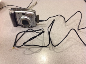
Inside the cable there is a flow of electrons, creating an electric current.

Inside the cable there is a flow of electrons, creating an electric current.

Even though I use my iPhone and iPad chargers several times each day, I usually don’t pay much attention to the actual electric processes occurring within each cable. My excuse is that I can’t see what static electric processes go on within the wires. However, when preparing for the Ritsumeikan Super Science Fair, I had a chance to look deeper into the electric physics of a Canon camera wire charger.

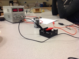
To create an effective power source for the camera, my RSSF team had to strip the charger’s cable. Once the cable’s outer casing was removed, two distinct sections of copper wires were exposed. In the center of the cable lay the positively charged wires, which were insulated by a thin tube of plastic rubber. The insulator separated the positive wires from the negative wires that lay on the cable’s outer ridge. The insulator is a non-metallic material with molecules tightly holding the atom’s electrons together, and is used to stop the spread of charge between the two wire sets. The copper wires were the conductors with free moving electrons, making electric charges flow easily along each wire.

The actual charge running through the wire was the flow of electrons. Usually, charge is transferred by the lost of electrons in the positive object and the gain in electrons in the negative object. The result is a flow of charges from the positive object to the negative object. However, when regarding the electrical flow in a wire, the positive charges are fixed, so there is only a flow of electrons from the negative wires to the positive wires.

Inside the cable there was a set of positive copper wires separated from a negative set of wires.

Inside the cable there was a set of positive copper wires separated from a negative set of wires.

In our experiment we used two power sources, a wall outlet and two 1.6V D-cell batteries. When measured with a voltage regulator both the outlet and the battery pack produced a voltage of roughly 3.3V. Voltage also described as electric potential is the difference between the electric charge between two points in a circuit. In the case of the batteries, the two points of charge would be the positive and negative plates located  inside each battery. The 1.6V of the D-cell batteries was produced by the difference of electric charge between the positive and negative plates.

Another important factor of the battery power source is capacitance. When the batteries were hooked up to the cell pack they formed a capacitor that could store up charge. Capacitance is the measure of how much charge a capacitor can store. Capacitance can be calculated by multipying the constant of permittivity of free space by the area of the capacitor’s charged plates and divided by the distance between the plates, C = ε0A/d. Although the two batteries were position side by side they were actually connected in a series, because the negative end of the first battery was hooked up to the positive side of the second battery. When capacitors are hooked up in a series, their total capacitance is less than than the capacitor’s individual capacitance. This concept occurs because the connection of the oppositely charged plates allows the charge to be shared equally along all capacitors.

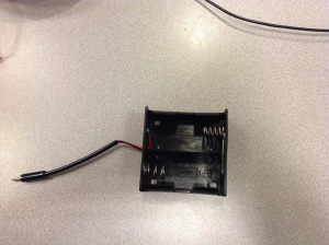
This battery housing held two D-cell batteries, arranging them in series.

This battery housing held two D-cell batteries, arranging them in a series.

When we ran the camera with the wall’s outlet it worked fine, but when we ran it on the battery pack the camera kept displaying a low battery signal and automatically shut off. We were confused to why the battery pack of equal voltage to the wall outlet could not run the camera. Our question was answered after we measured the amount of amperes running through each power source. The current regulator showed a significantly lower ampere value for the running battery pack than for the outlet power source. This showed that even though the two power sources had equal voltages, there was less charge and flow of electrons in the battery, resulting in an ineffective power source. Our team is still not sure why there is a significant less amount of charge running through the batteries, but this is a problem that we will have to solve to run the camera effectively on an independent power source.

Physics in a Thunderstorm: Sound

A thunderstorm is an example of both sound and light waves.

A thunderstorm is an example of both sound and light waves.

During these winter days, the weather is sometimes wet and stormy in Hawaii. Over the weekend we experienced a thunderous rain storm lasting the entire day. Usually I try to avoid the booming thunder and shocking lighting, but after learning about waves in physics, I found myself thinking more about the thunderstorm.
During the storm, I first saw the flashing lights of thunder and then heard the thunder’s rumble. Both the lighting and thunder travels in waves: light waves and sound waves. Light waves are transverse waves, because its particles of motion travel perpendicular to the direction of the wave. Sound waves are longitudinal waves because its particle of motion travel parallel to the direction of the wave. Both types of waves have a specific wavelengths, but the structure of each type varies. In a light wave the wavelength is the distance of the length between two adjacent troughs or crests. In a sound wave the wavelength is the distance of the length between the centers of two adjacent compressions or expansions.
In all wave, the wavelength of the wave depends on the frequency of the wave. Frequency is the number of cycles completed per second; therefore, the higher the frequency the shorter the wavelength. The frequency is also inversely proportionate to the period of the wave. Period is the time required to complete one cycle. Specifically, in a sound wave frequency and the period is determined by the pitch of the sound. The higher the sound of the note the higher frequency of the wave and therefore the smaller the period. Since I know that the pitch of the thunder was really low, the wave length of sound for thunder must have had a low frequency and a long period.
The amplitude of the sound wave is the distance between the wave’s equilibrium mark and the top of the crest or bottom of the trough. Sound wave’s amplitude depends in the volume of the sound. The greater the volume the greater the amplitude. Since I could hear the thunder from miles away, the amplitude of the waves length at the source of the sound must have been really great.
Although the frequency, period, and amplitude depend on pitch and volume, the speed of a wave is not affected by these variables. Instead a speed of a wave depends on the matter of which the wave is traveling though. Sound can travel through any matter, but its velocity is greatest in solids, then liquids, and slowest in gasses. Since the majority of the thunder’s sound reached my ear though the air, the speed of the sound wave was relatively slow. Temperature and air density can also affect the velocity of the sound waves. Since I saw the flash of lighting a good few seconds before I heard the thunder, the light waves obviously travel faster than sound waves.

Physics on a Stove: Thermodynamics

When the pan is directly above the flames, heat is transferred through radiation.

When the pan is directly above the flames, heat is transferred through radiation.

Every time I need to boil water on my gas oven stove, I think of all the thermal activities occurring in the metal pan. Although I cannot see all of the processes occurring, I now know that several concepts of thermodynamics can be expressed in a single pan. This morning when I heated up water to make oatmeal, I noticed that right before I set the pan on the stove, the stove’s flames did not touched the pan, but heat was still transferred. This transfer of heat is called radiation, when heat is transferred by electromagnetic waves. When I set the pan directly on the stove, the heat then transferred through conduction, meaning the thermal energy flowed directly from the stove and flame’s molecules to pan’s molecules.

When heat was introduced to the pan and water, thermal expansion took place, because when objects obtain a change in temperature they undergo a change in length or volume. Since the pan and water where heated up they expanded to the volumes, according to the equation ΔV=β Vi ΔT. Since the coefficient of volume expansion for water is much greater than the coefficient of volume expansion for the steel pan, the water’s expansion is greater.

Thermal equilibrium or 0th Law of Thermodynamics is also reached in the process of boiling water. When the water inside the pan begins to boil, the pan and the stove come to the same temperature. Since the pan and water are at the same temperature the water is also in thermal equilibrium with the stove. When all three objects are in thermal equilibrium there is no more flow of heat.

Conduction occurs when heat is transferred directly from the stove's molecules to the pan's molecule. Eventually thermal equilibrium will be reached.

Conduction occurs when heat is transferred directly from the stove’s molecules to the pan’s molecule. Eventually thermal equilibrium will be reached.

However, prior to reaching thermal equilibrium a certain amount of heat had to flow from the stove to the pan and water. That heat can be calculated by the equation Q=mc ΔT, where Q is the amount of heat flow per kilogram, m is the mass of the heating object, c is the specific heat, and ΔT is the change in the temperature. To reach thermal equilibrium, heat had to first transfer to the pan then transfer to the water. Since water has a much higher specific heat than steel, it takes a longer time for the water to reach thermal equilibrium than for the steel to do the same.

If I was to place a lid on the pan during the heating process, I would create an isochoric process, where volume is constant, but temperature varies with pressure. When the temperature of the pan increases the molecules within the pan would begin to move faster, but the lid would keep them from escaping. The fast moving gas particles would bounce against the pan’s walls at a higher rate, increasing the pressure inside the pan. In this isochoric process there is not work done by this system, because volume is neither compressing nor expanding. However, the internal energy increases because the temperature also increases. In all isobaric processes the change in internal energy is equal to the heat transferred from the system.

Physics on a Lake: Density

My sister rowing our boat on the lake at Central Park

My sister rowing our boat on the lake at Central Park

When I went to New York for a family vacation, my sister and I experienced new and exciting adventures. Although we enjoyed all the shopping amongst the brightly lit signs at Times Square, we also enjoyed leaving the city life to visit Central Park. At the park we rented a small rowboat to use in the park’s lake. The rowboat was fun to maneuver in the pond, but I remember thinking how disgusting it would be if our boat began to sink and we were forced to swim in the lake’s dirty water. Luckily, we did not sink and made it back to the dock all safe and dry. We owed our dryness to the natural properties of water that allowed our rowboat to float on the lake.

Our rowboat did not sink to the lake’s bottom, because the density of the boat and us was much less than the density of water. Density can be calculated by dividing the mass of the object divided by the volume of water the object displaces, ρ=m/v. The density of the lake’s water was around 1.0×10³ kg/m³, so the density of my sister and I inside the boat must have been less than that for us to float. The specific gravity of our boat was the ratio of our system’s density to the density of the lake.

Thanks to water density our boat did not sink

Thanks to water density our boat did not sink

On dry land our boat would have had a downward force of mg, our weight, and an upward normal force. When submerged in water, the boat still had the same downward force, but had no upward normal force. Instead buoyant force acted upward on the boat. Buoyant force is the upward force water exerts on a submerged object and is calculated by FB=ρvg.

 The buoyant force is the reason why our weight in the water appears to be smaller than our weight on dry land. The mass of the boat remained constant, but water exerted an upward force making the boat’s weight appear smaller.

Physics on Vacation: Rotation and Torque Equilibruim

As I mentioned in my previous post, my family takes several trips to Seattle, Washington. On one of our past trips I remember visiting another grand playground with interesting play equipment. The playground was equipped with slides, swings, a rock-climbing wall, and a giant concrete statue of a salmon, but I most clearly remember having a super time with my sister on a particular playground structure. This playground structure was similar to a seesaw but instead of just having a giant hinge located at the center it hade two giant springs on each side of the fulcrum. The springs allowed my sister and I to bounce up and down in opposite directions, but when we were still the structure would always be aligned with the horizon. The spring seesaw demonstrates the idea of rotation versus torque at equilibrium.

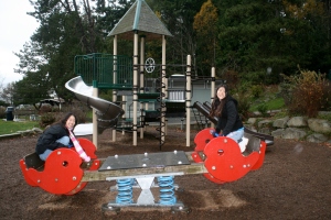
Riding on the spring seesaw

Riding on the spring seesaw

Torque is defined as the force needed to start or stop a rotation. To calculate torque both the position and direction of the force matters, because the equation of torque is τ=Fdsinθ. In the case of the seesaw all the forces in the system were acting perpendicular to the wooden plank, so θ is equal to 90° and the equation can be rewritten as τ=Fd. The d represents the distance of the forces relative to the fulcrum of the system. On the seesaw the fulcrum was located at the center of the wooden plank.

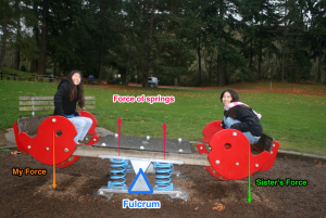
When the seesaw was perfectly balanced, the net torque was zero, because all the torques on each side of the fulcrum canceled out. The forces acting on the seesaw included my and my sister’s downward force and the upward forces of the springs. At that time my sister and I weighted roughly about the same weight, so we exerted the same amount of force. However, since we were located on opposite sides our direction of torque differed. When I sat on the left side of the fulcrum I caused the seesaw to rotate in a positive direction and my sister on the right caused it to rotate in a negative direction. Since the springs provided an upward force, the spring on the left caused the seesaw to move in a negative direction and the spring on the right in a positive direction. The equal but opposite torques cancelled each other out allowing the seesaw to be balanced.

Experiencing the forces contributing to torque and the seesaw's rotation

Experiencing the forces contributing to torque and the seesaw’s rotation

The spring seesaw was easier to balance then a normal seesaw, because the springs allowed for more stability. Even if my sister and I were not totally equal in weight, the springs would adjust, compressing more on the heavier side.